
TECHNICAL WHITEPAPER
Selecting Quick Disconnects for AI Data Center Liquid Cooling
An Engineer’s Guide
How to evaluate flow, pressure, fluid loss, blind-mate tolerance, serviceability, coolant compatibility, and system integration across the complete cooling loop.
Download the Guide (PDF)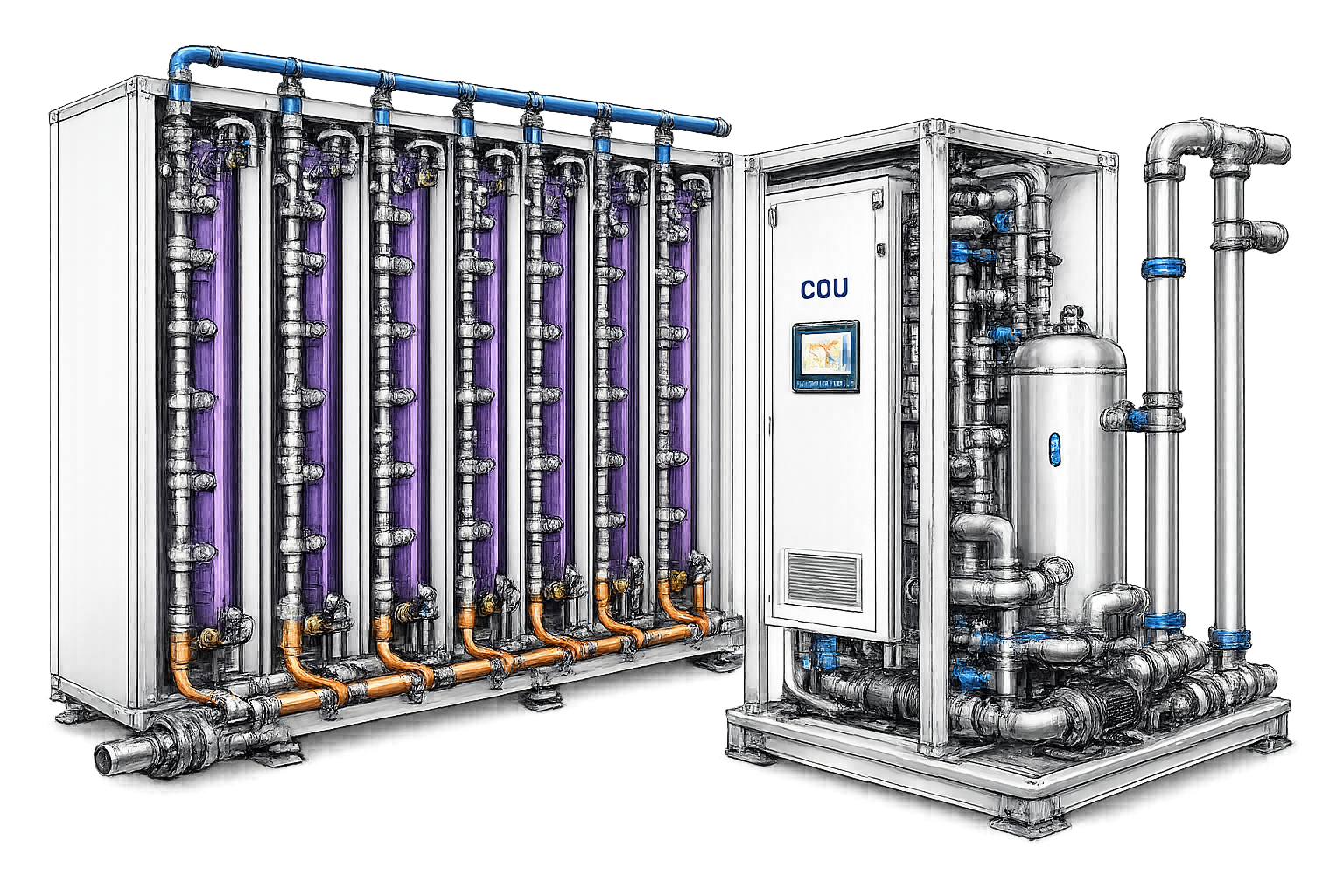
Connector selection starts with the cooling-loop requirement
Quick-disconnect selection should begin with the connector’s role in the coolant path and the system’s measurable requirements. Engineers should evaluate flow demand, pressure rating and pressure drop, fluid loss, alignment tolerance, coupling cycles, service access, coolant and material compatibility, installation method, cleanliness, traceability, and qualification requirements.
The appropriate QD depends on where it operates in the cooling architecture and how its measurable performance supports system flow, packaging, maintenance, and repeatable connection requirements.
What engineers will learn
Map QDs to the cooling loop
Differentiate tray/cold-plate, rack/blind-mate, and CDU/source-line connection requirements.
Evaluate hydraulic performance
Compare flow demand, Cv or rated flow, working pressure, pressure drop, and fluid loss.
Assess blind-mate reliability
Consider radial and angular misalignment, repeatable engagement, and installation conditions.
Plan for serviceability
Account for hand clearance, routing, disconnect behavior, hardware replacement, and maintenance conditions.
Verify compatibility
Review coolant, materials, terminations, cleanliness, traceability, and qualification requirements.
Use a repeatable selection framework
Apply measurable criteria, comparison data, and a qualification checklist to support engineering decisions.
Where quick disconnects fit in the liquid cooling architecture
Quick disconnects operate in different service environments across the coolant path. Tray-level, rack-level, and source-line connections place different demands on flow, packaging, alignment, and serviceability.
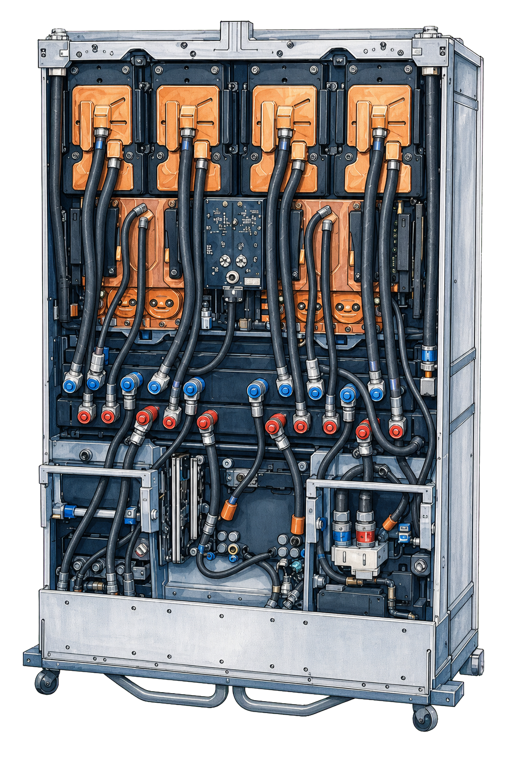
Tray / Cold-Plate Connections
MQD Series
High-density connections at the tray or cold-plate level.
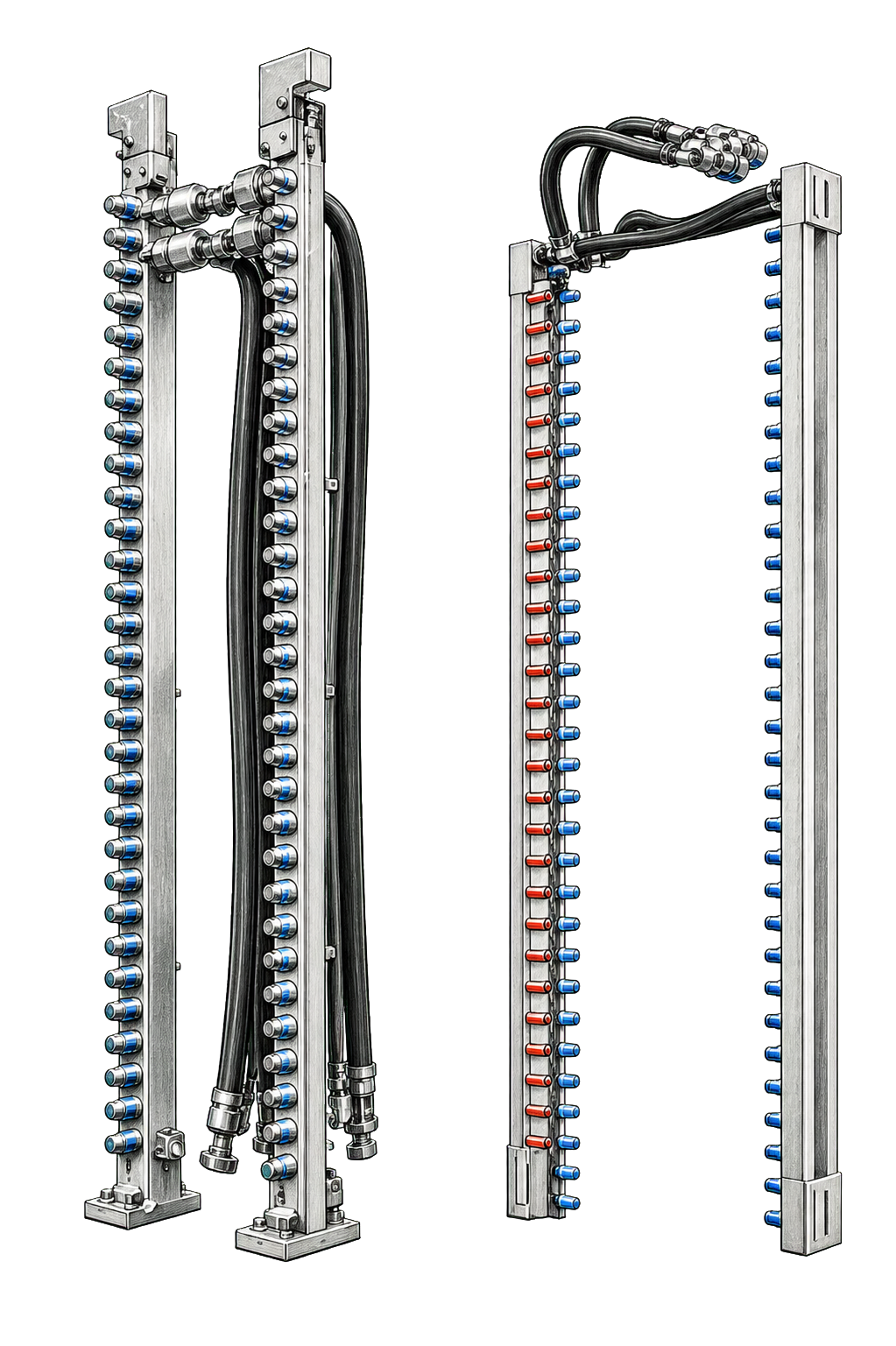
Rack / Blind-Mate Interfaces
UQDB and BMQC Series
Blind-mate connections between racks, manifolds, and coolant distribution interfaces.
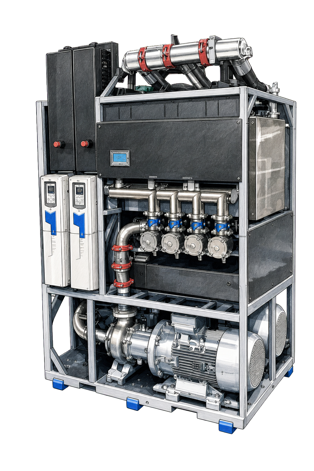
CDU / Source-Line Infrastructure
LQC and SHQD Series
Higher-flow connections for CDUs and facility source-line infrastructure.
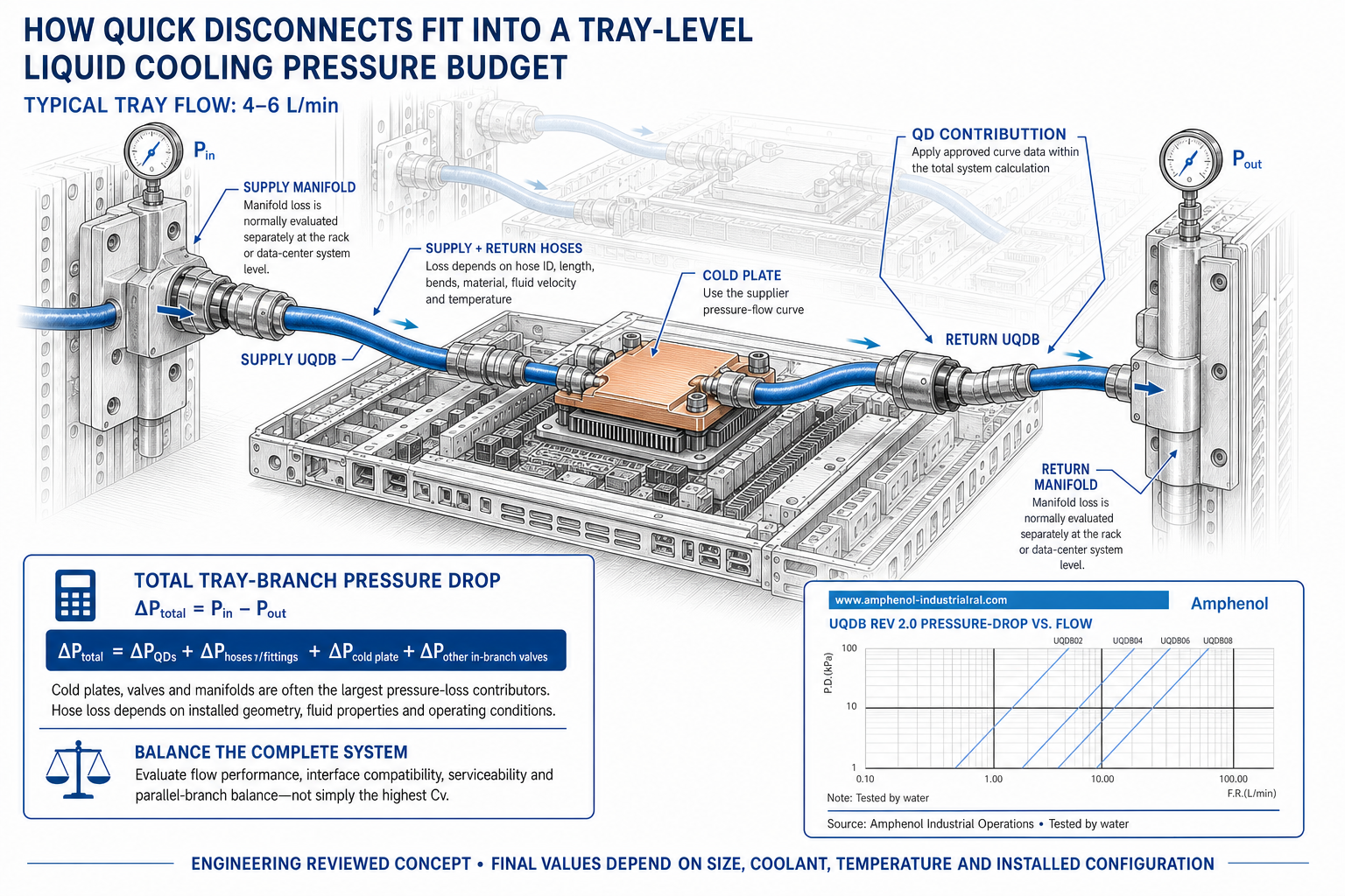
How Quick Disconnects Fit Into a Tray-Level Liquid Cooling Pressure Budget
Illustrative UQDB Rev 2.0 example at a typical tray flow of 4–6 L/min
Pressure drop should be evaluated across the complete tray branch rather than at an individual connector in isolation. At the target flow rate, engineers combine the pressure losses associated with the supply and return QDs, cold plate, hoses, fittings and other in-branch valves to determine total branch pressure drop as Pin − Pout. QD performance is one input to the total system pressure budget. Connector selection should balance flow performance with interface compatibility, serviceability and consistent flow distribution across parallel tray branches.
How to select quick disconnects for liquid cooling
QD selection should balance measurable hydraulic performance with installation, maintenance, material, and qualification requirements.
Flow and pressure
Evaluate required flow, Cv or rated flow, working pressure, maximum operating pressure where applicable, and the connector’s contribution to system pressure drop.
Fluid loss and sealing
Consider fluid loss during disconnect, sealing behavior, service environment, and the consequences of leakage around sensitive electronics or infrastructure.
Blind-mate tolerance
For blind-mate applications, evaluate radial and angular misalignment separately, along with engagement repeatability and mechanical installation conditions.
Serviceability
Account for access, hand clearance, hose routing, disconnect behavior, coupling cycles, hardware replacement, and maintenance procedures.
Coolant and material compatibility
Verify coolant chemistry, wetted materials, seals, termination type, and application-specific compatibility requirements.
Cleanliness and traceability
Review applicable cleanliness controls, packaging, inspection, and approved traceability capabilities as part of deployment and issue-review requirements.
Hydraulic performance
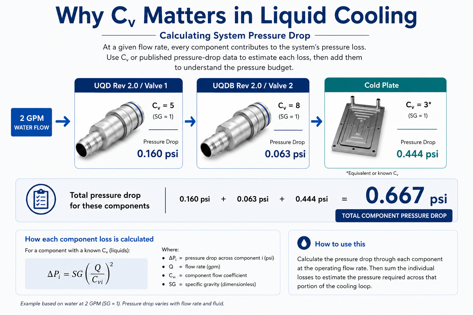
Understanding Cv and pressure drop Flow performance is an important consideration when selecting quick disconnects for a liquid cooling system. At a given flow rate, each component in the cooling loop contributes to the system's overall pressure loss. Cv provides engineers with a way to evaluate that contribution. The example below illustrates how pressure drop can be calculated across individual components and combined to help understand the pressure budget for a portion of the cooling loop.
What this means for quick disconnect selection
Cᵥ provides one way to compare hydraulic performance, but QD selection should consider the complete coolant path. Engineers should evaluate pressure loss at the intended flow rate alongside interface type, serviceability, fluid containment, coolant compatibility and system integration.
Quick disconnect selection matrix
Use this comparison framework to evaluate product families by cooling-loop location and measurable performance. Final product selection should be validated against application requirements and current product documentation.
| Series | Application | Cv / Pressure Drop | Working Pressure | Max Operating / Safe Pressure | Flow Rate | Fluid Loss (mL) | Radial Misalignment | Angular Misalignment | Mating Cycles |
|---|---|---|---|---|---|---|---|---|---|
| MQD | Tray / Cold-Plate | Cᵥ: -02 >0.4; -03 >0.7; -04 >1.4 | 0-100 psi | Safe pressure: 300 psi | 02=2.08L/min, 03=4.54L/min, 04=6.81L/min | 02: < 0.003 03: < 0.01 04: <0.005 | N/A | N/A | Up to 5,000 |
| UQD Rev 2.0 | Manual quick disconnect for modular liquid-cooling loops | Cᵥ: up to 5.1; rated flow up to 17.79 L/min | 0-100 psi (maximum operating) | Minimum burst pressure: 300 psi | 02: 2.27 04: 6.44 06: 11.36 08: 17.79 | 02: 0.0009 04: 0.017 06: 0.015 08: 0.024 | N/A | N/A | Up to 5,000 |
| UQDB Rev 2.0 | Rack interface | Cᵥ: up to 4.9; rated flow up to 17.79 L/min | 0-100 psi (maximum operating) | Minimum burst pressure: 300 psi | 02: 2.27 04: 6.44 06: 11.36 08: 17.79 | 02: 0.0009 04: 0.017 06: 0.015 08: 0.024 | 1.0 mm (+0.3 / 0) | N/A | Up to 5,000 |
| BMQC | Rack interface | Cᵥ: 1.32 typical | 0-0.35 MPa | Safe pressure: 1.0 MPa | Up to 10 LPM | 0.025 ml | +/-5 mm | +/-2.7 degrees | Up to 1,000 |
| LQC | CDU / Source-Line | Cᵥ: 22; rated flow up to 120 L/min | 0-1 MPa | Safe pressure: 2 MPa | Up to 120 LPM | <0.005 mL | N/A | N/A | Up to 100 |
| SHQD | CDU / Source-Line | Cᵥ: by size: 1 in. = 30; 1.5 in. = 90; 2 in. = 136 | 0-1 MPa | Safe pressure: 2 MPa | Refer to current approved product data | 1”(5ml.) / 1.5”(8ml.) / 2”(12ml.) | N/A | N/A | Up to 500 |
| XBMC | BMF02 | XPO optical module | Cᵥ: 0.17 | 100 psi | minimum burst pressure 200 psi | up to 0.8 LPM 0.7 LPM at 1.05 psi 0.4 LPM at 0.43 psi | Less than 0.020ml | +/-0.5 | N/A | Up to 500 |
Get the complete engineering guide
Download the full PDF for detailed application guidance, technical tables, qualification considerations, and engineering context.
Download the Guide (PDF)Engineering expertise and AI data center contacts
FIELD APPLICATION ENGINEER

Jensen Stenberg
Email Jensen
jstenberg@amphenol-aio.com
CONNECT WITH AN AI DATA CENTER EXPERT


Engineering questions about liquid cooling quick disconnects
How should engineers select a quick disconnect for liquid cooling?
Start with the connector’s location in the coolant loop and the system requirements at that interface. Evaluate flow demand, pressure and pressure drop, fluid loss, alignment tolerance, service access, coupling cycles, coolant and material compatibility, cleanliness, traceability, and qualification requirements.
How do flow and pressure affect QD selection?
The QD must support the required coolant flow while remaining within the system’s pressure limits and pressure-drop budget. Engineers should compare published Cv, rated-flow, working-pressure, and pressure-drop data using consistent operating conditions.
How should quick-disconnect pressure drop be included in a liquid-cooling pressure budget?
Evaluate the QDs as part of the complete coolant path at the intended flow, fluid and temperature. Total tray-branch pressure drop is measured as Pin − Pout and includes the QDs, cold plate, hoses, fittings and other in-branch restrictions.
Why does blind-mate tolerance matter in rack-level liquid cooling?
Blind-mate interfaces must repeatedly connect when components cannot be manually aligned at the coupling. Radial and angular misalignment should therefore be evaluated separately along with installation geometry, repeatability, and service conditions.
How should serviceability influence connector selection?
Service conditions affect access, hose routing, disconnect behavior, coupling frequency, replacement procedures, and the potential consequences of fluid loss. A connector that meets hydraulic requirements may still be unsuitable if it cannot be safely and reliably serviced in the available space.
What coolant and material compatibility factors should engineers verify?
Engineers should verify coolant chemistry, wetted materials, seals, connection terminations, operating temperature, cleanliness requirements, and application-specific qualification requirements before approving a QD.
Related Liquid Cooling Resources
Liquid Cooling Connectors for AI Data Centers: Beyond OCP Compliance

Liquid Cooling Systems | Reliable Quick Disconnects

Liquid Cooling Solutions Videos

Connect with our Team
Engage with our skilled sales and technical teams who are committed to offering you personalized assistance tailored specifically to your project requirements.